
Creating and configuring the FlowVision project.
To prepare a FlowVision project for FSI, you should first be comfortable with assembling regular FlowVision CFD projects. If you don't yet know how to do this, the hands-on Quick Start example and the FlowVision Tutorial (which also contains a section on FSI) will help you.
After creating the CFD project, we proceed to setting up the FSI interaction. Let's make a note of the key points:
- Working with moving bodies
- Creating a connector
- External communication settings
Working with moving bodies
What to look for when setting the ‘Moving Body’ modifier?
Checking for self-intersections:
The first thing you should do after importing an object into FlowVision is check the imported object for self-intersections (right click on the imported object> check geometry for self-intersections). If there are no self-intersections, then you can continue on and create the Moving body modifier. If the geometry does have self-intersections, FlowVision will not be able to simulate this project. In this case, you will have to fix the geometry in Abaqus (if you created it there) or in a CAD package (if the Abaqus project was prepared on the basis of CAD geometry), and correct it to be in accordance with FlowVision geometry requirements (you can read about them here and here).
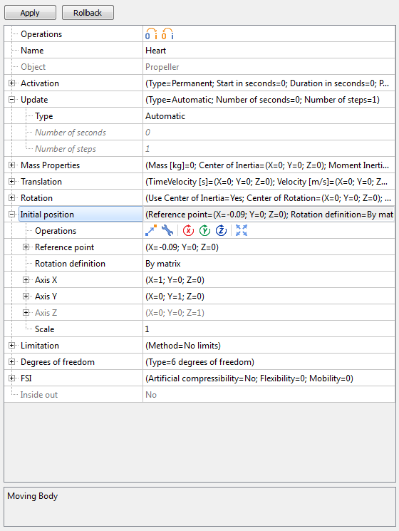
Body positioning:
It is extremely important to correctly position the moving body within the computational domain (parameter - Initial position). For some tasks this is critical and the entire joint calculation may suffer if the body is positioned incorrectly.
Resizing the moving body:
Another important point is the size of the moving body. If the Abaqus project is using a measurement system other than SI, then the moving body from Abaqus must be rescaled in FV by applying a scale factor in the properties of the moving body. Scaling should be performed like this, since this is the only method that ensures rescaling at each exchange step (not to be confused with Transformation).
Note! When applying a Transformation operation, you lose the connection with the original form of the geometric object. Therefore, for joint calculations, the initial position and scale should be adjusted only within the properties of the moving body.
Creating a connector
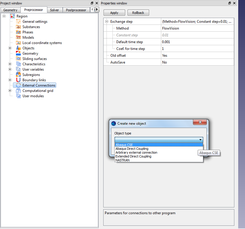
As described in the 'Configuring the Abaqus project' section, an external connection with Abaqus is established using one of the two types of connectors : ‘Direct Coupling’ or ‘CSE-connector’.
To create a link, right-click on the External Links section in the project tree - "Create New Object", and select the required connector.
External communication settings
Among the connector settings, stress / heat relaxation should be noted. The first is used in models with deformation due to external loads, and the second is for problems with deformation due to temperature. For both types of relaxation, you can set:
- scale factor (loads will be scaled according to the specified value)
- start / end in steps (you can start transferring loads not from step zero, but later)
- initial / final coefficients (these reflect how the loads will be transferred - immediately and in their entirety or gradually with some gradient (ramping))
For example, you can set up the load transfer to happen smoothly over steps 1 to 50, by setting the following values:
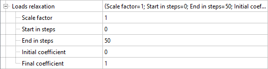
There are similar settings for the transfer of heat loads.
These settings are needed to smoothly transfer the load from FV to ABQ, which will ensure a more stable solution at the beginning of the calculation. If these settings are not used, then your calculation may fall apart due to loads being applied instantaneously, which will result in large displacements of the finite element nodes in the FE-complex.